|
Measurement of little displacements by a magnet and a coil by Gerhard Höhne The measurement of an inconspicuous effect by simple means is an impressive experiment usually. For instance the students are very interested in the question, how the tiny deformation in a wall under the pressure of a hand can be measured by a coil and a magnet.
1. Measurement of a deformation and vibration of a wall
|
||
|
|
|
|
|
fig. 1 |
fig. 2 |
fig. 3 |
|
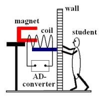
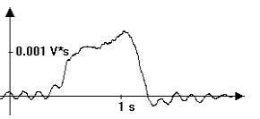
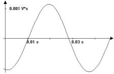
In fig. 1 a student is shown, who pushes against a wall of a classroom (thickness = 18 cm). He causes a tiny deformation in the wall, which is measured by a magnet and a coil as shown in fig.1. A coil with 24000 windings is fastened at the wall and a magnet is fastened on a table before the wall. One pole of the magnet is inserted into the coil. While the deformation of the wall the magnet causes an induction-voltage U in the coil proportionally to the speed of the coil. This voltage is measured by a PC + AD-converter. The PC is calculating the time-integral of U and produces a diagramm, which shows this integral in dependence of the time. The integral is proportional to the displacement of the coil. Fig. 2 shows the deformation under a continuous pressure and fig. 3 shows the vibration of the wall after a push.
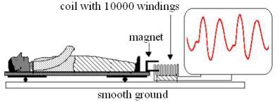
2. Registration of a ballistocardiogram A student lies on a board which is kept on rolls. If blood is pumped out from a ventricle, the body moves itself to preserve the Centre-of Gravity contrary to the flow direction of the blood. The PC ist drawing a ballistocardiogram. To registrate the moving a magnet is fastened to the one end of the board, the one pole is surrounded by a coil with 10000 windings next to the board (integral of the voltage !) .
fig. 4
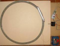
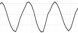
The following experiment leads to the understanding of these facts: A circular model-rail is built up on a board (fig. 6), which is underlaid with rolls (rolldiameter = 4 cm). These rolls allow a movement of the board to the left or right. A rail-vehicle rolls on this circle. If the vehicle runs to the left or to the right, the board glides in the opposite direction. The t-s-diagram in fig. 7 shows the movement of the board. The displacement of the board is measured by a magnet and a coil arranged at the left side of it.
fig . 5 fig. . 6
|
||